Channel Nuts and Load Data, End Caps, Closure Strips, Flat Fittings
"U" Shape Fittings, Pipe/Tube Clips and Brackets
Beam Clamps
Clamps are designed to be used with W, M, S and HP Shape beams, Standard C and Miscellaneous MC Channels, Angles and Structural Tees. Clamps must be used in pairs mounted in opposite directions where indicated. For beam clamps with HG finish, standard hardware is EG finish.
Material
Fittings, unless noted, are made from hot-rolled, pickled and oiled steel plates, bar, strip or coil, and conform to one or more of the following specifications: ASTM specifications A575, A576, A635, A1011 SS GR 33, A1011 HSLAS GR 45 or A36. All fittings meet or exceed physical properties of ASTM A1011 GR 33. The pickling of the steel produces a smooth surface free from scale.
Finishes
Fittings are available in:
Electro-galvanized (EG), conforming to ASTM B633 Type III SC1;
Hot-dipped galvanized (HG), conforming to ASTM A123 or A153 and
Application
All parts drawings illustrate only one application of each fitting. In most cases many other applications are possible. The channels shown in the illustrations are P1000, 15⁄8″ square, except where noted otherwise.
All 9⁄16″ diameter holes use 1⁄2″ x 15⁄16″ hex head cap screws and 1⁄2″ nuts – P1010, P3010, P4010 or P5510 – depending on the channel used. Nuts and bolts are not included with the fitting and must be ordered separately.
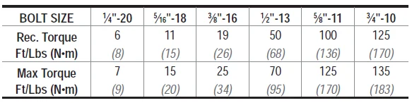
Design Bolt Torque
Set Screw Torque
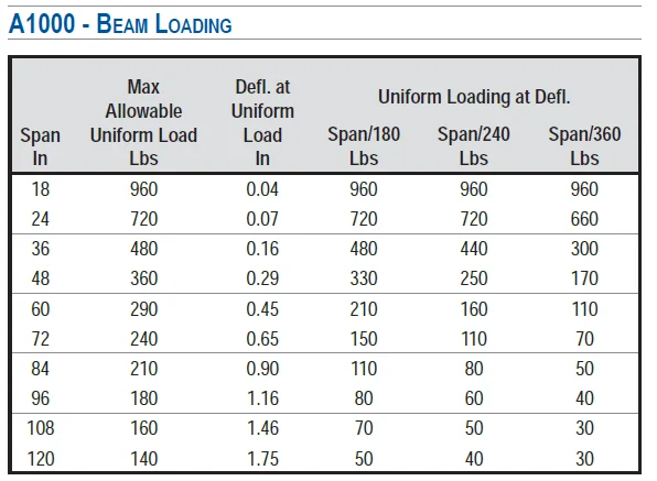
Design Load
Design load data, where shown, is based on the ultimate strength of the connection with a safety factor of 2.5, unless otherwise noted.